With my BananaPi up and running again, it’s time to put it back in the server cabinet. But it’s a little bit of a mess down there, and I decided my new 3D modeling skills could help me build a new home for the proxy.
Find the Model
When creating a case for things, having a 3D model of the thing you are creating becomes crucial. Sometimes, you have to model it yourself, but I have found that grabcad.com has a plethora of models available.
A quick search yielded a great model of the Banana PI. This one is so detailed that it has all of the individual components modeled. All I really needed/wanted was the mounting hole locations and the external ports, but this one is useful for much more. It was so detailed, in fact, that I may have added a little extra detail just because I could.
General Design
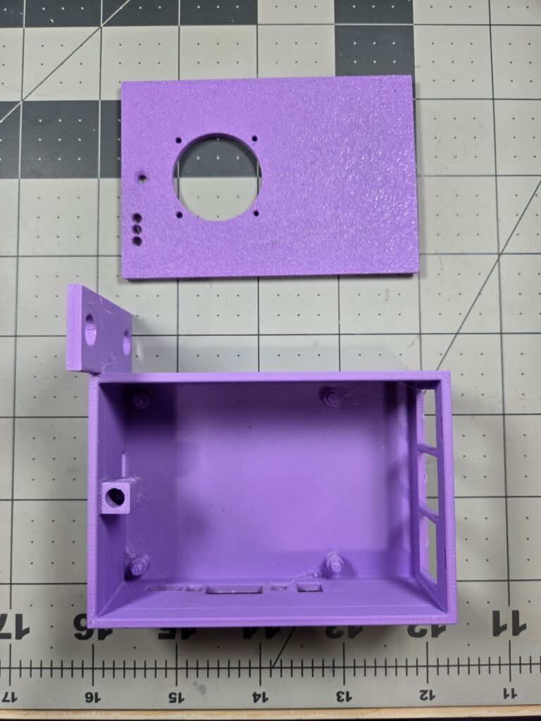
This case is extremely simple. The Banana Pi M5 (BPi from here on out) serves as my reverse proxy server, so all it really needs is power and a network cable. However to ensure the case was more useful, I added openings for most of the components. I say most because I fully enclosed the side with the GPIO ports. I never use the GPIO pins on this board, so there was really no need to open those up.
For this particular case, the BPi will be mounted on the left rack, so I oriented the tabs and the board in such a way that the power/HDMI ports were facing inside the rack, not outside. This also means that the network and USB ports are in the back, which works for my use case.
A right-mount case with power to the left would put the USB ports at the front of the rack. However, I only have one BPi, and it is going on the left, so I will not be putting that one together.
Two Tops
With the basic design in place, I exported the simple top, and got a little creative.
Cool It Down…
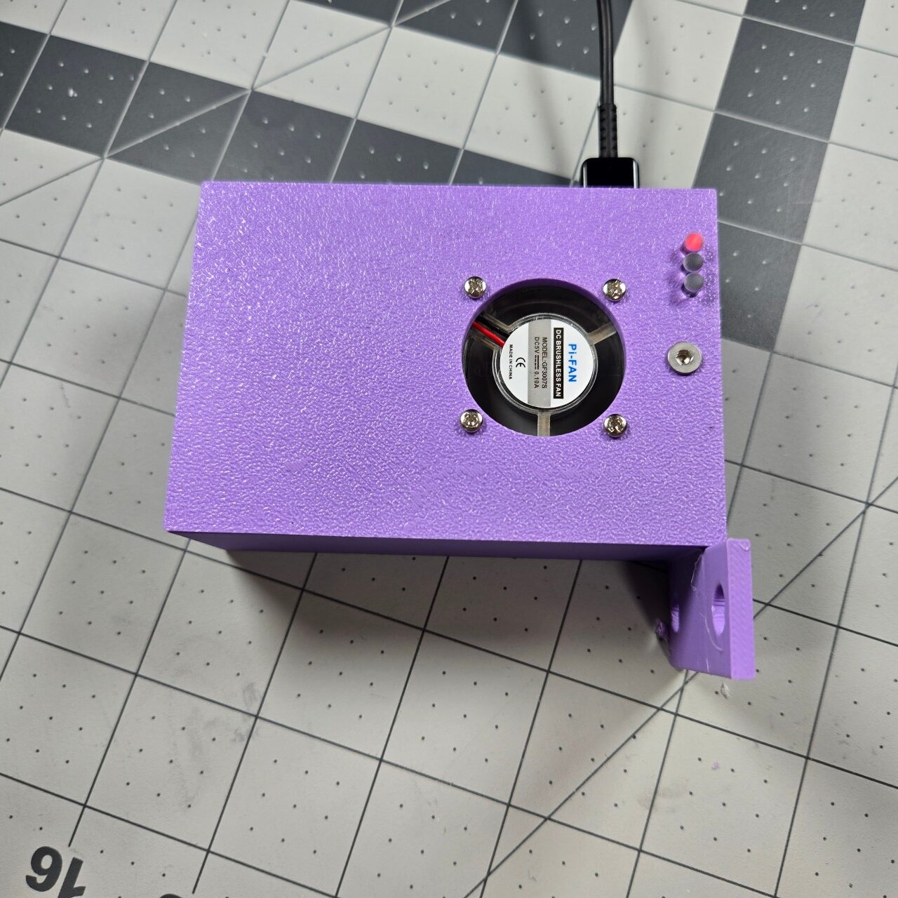
My BPi kit came with a few heatsinks and a 24mm fan. Considering the proxy is a 24×7 machine, and it is handling a good bit of traffic, I figured it best to keep that fan in place. So I threw a cut-out in for the fan and its mounting screws.
Light it up!
On the side where the SD card goes, I closed off everything except the SD card itself. This includes the LEDs. As I was going through the design, I thought that it might be nice to be able to peek into the server rack and see the power/activity LEDs. And, I mean, that rack already looks like a weird Christmas tree, what are a few more lights.
I had to do a bit of research to actual to find the actual name for the little plastic pieces that can carry LED lights a distance. They are called “light pipes.” I found some 3mm light pipes on Amazon, and thought that would be a good add to the build.
The detail of the BPi model I found made this task REALLY easy: I was able to locate the center of the LED and project it onto the case top. A few 3mm holes later, and the top is ready to accept light pipes.
Put it all together
I sent my design over to Pittsburgh3DPrints.com, which happens to be about two miles from my house. A couple days later, I had a PLA print of the model. As this is pretty much sitting in my server cabinet all day, PLA is perfect for this print.
Oddly enough, the trick to this one was to be able to turn off the BPi to install it. I had previously setup a temporary reverse proxy as I was messing with the BPi, so I routed all the traffic from the BPi to the temp proxy, and the shutdown the BPi.
Some Trimming Required
As I was designing this case, I went with a best-guess for tolerances. I was a little off. The USB and audio jack cutouts needed to be taller to allow the BPi to be installed in the case. Additionally, the stands were too thick and the screw fan holes too thin. I modified these designs in drawings, however, for the printed model, I just made them a little larger with an Exact-o blade.
I heat-set a female M3 insert into the case body. I removed the fan from the old case top and attached it to my new case top. After putting the BPi into place in the case bottom, I attached the fan wires to the GPIO ports to get power. I put the case top on, placing the tabs near the USB ports first. Screwed in an M3 bolt and dropped three light pipes into the case top. They protruded a little, so I cut them to sit flush while still transmitting light.
Finished Product


Overall I am happy with the print. From a design perspective, having a printer here would have alleviated some of the trimming, as I could have test printed some smaller parts before committing.
I posted this print to Makerworld and Printables.com. Check out the full build there!